Oct 20, 2026Flow Meter Selection Guides
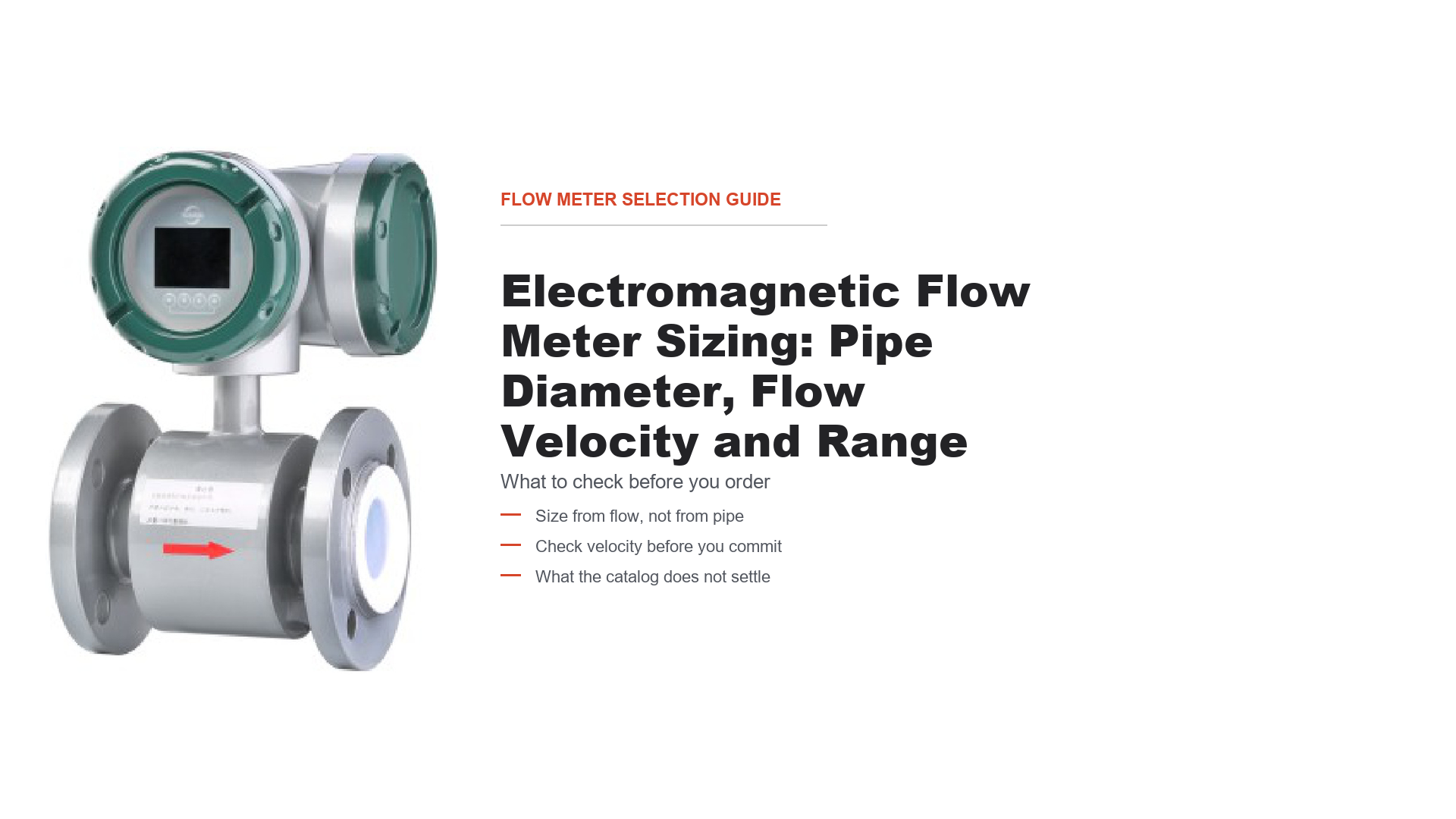
Electromagnetic Flow Meter Sizing: Pipe Diameter, Flow Velocity and Range
Size an LD electromagnetic flow meter from minimum, normal and maximum flow: check velocity, pressure and configuration against the published DN table.
Most magmeter questions arrive as "which size do I need", and most answers arrive as a velocity table. Neither is quite the right starting point. The size you order follows from two numbers you already have — your minimum and maximum flow — checked against one number the manufacturer publishes — the velocity band — and cross-checked against a table of nominal sizes.
This guide works that sequence on the LD electromagnetic flow meter, using its published size table. Where the catalog does not answer something, this guide says so rather than borrowing a figure from another manufacturer.
What decides the size
Three inputs drive the initial selection, in this order:
- Your flow range — minimum, normal and maximum, in a single unit.
- The measuring velocity — the speed at which the sensor still performs.
- The published size table — which nominal size covers your range at that speed.
These three get you to a candidate size. They are not the only constraints on what you can actually order: working pressure, the medium and its conductivity, the liner and electrode materials, the pipework you have, and the installation conditions can each eliminate a candidate the flow range alone would have allowed. A selection is only finished when all of them have been checked.
By contrast, the pipe you already have, the size of the old meter and the space in the skid do not decide the bore — if they conflict with the sizing, you adapt the pipework with reducers rather than changing the size to match the pipe.
A magmeter measures velocity: the conductive liquid moving through the magnetic field generates a voltage proportional to speed. Flow rate and velocity are locked together by the cross-sectional area, so a given size can only pass so much flow before the velocity leaves the band, and only so little before it falls out the bottom. That is the sizing problem in one sentence.
The two numbers Yuanda publishes
Parameter | Published value | Where |
|---|---|---|
Size range | DN15 to DN2200 | catalog p.40, p.41 |
Flow velocity | 0.3–5 m/s, extended to 10 m/s | catalog p.40 |
Accuracy | ±0.5% to ±1.0% | catalog p.40 |
Conductivity | ≥5 μS/cm | catalog p.40 |
Medium temperature | ≤120 °C integrated; ≤150 °C split (80 °C with rubber liner) | catalog p.40 |
Working pressure | 4.0 MPa at DN15–80, 1.6 MPa at DN100–400, 1.0 MPa at DN450–1000, 0.6 MPa at DN1200–2000, 0.25 MPa at DN2200 | catalog p.41 |
Output | 4–20 mA / frequency or pulse / RS485 | catalog p.40 |
Power | 220 VAC or 24 VDC | catalog p.40 |
Two things about the velocity band are worth stating plainly, because they are easy to misread.
It is a single band for the family, not a per-liner figure. The catalog gives 0.3–5 m/s for the LD series. It does not publish separate bands for chloroprene, polyurethane, PTFE, PFA or F46 liners, or for different electrode materials. If your application sits near either end of the band, that is a factory question, not something to settle from the table.
The table is narrower than the band at the low end. This is the single most useful observation in this guide, and it comes from checking the two published sources against each other — see the velocity check below.
The size table
This is the published flow range for each nominal size, transcribed from the catalog.
DN | Working pressure (MPa) | Flow range (m³/h) |
|---|---|---|
15 | 4.0 | 0.32–3.2 |
20 | 4.0 | 0.56–5.6 |
25 | 4.0 | 0.9–9 |
32 | 4.0 | 1.5–15 |
40 | 4.0 | 2.3–23 |
50 | 4.0 | 3.5–35 |
65 | 4.0 | 6–60 |
80 | 4.0 | 9–90 |
100 | 1.6 | 14–140 |
125 | 1.6 | 20–200 |
150 | 1.6 | 30–300 |
200 | 1.6 | 56–560 |
250 | 1.6 | 90–900 |
300 | 1.6 | 125–1250 |
350 | 1.6 | 175–1750 |
400 | 1.6 | 230–2300 |
450 | 1.0 | 290–2900 |
500 | 1.0 | 350–3500 |
600 | 1.0 | 510–5100 |
800 | 1.0 | 900–9000 |
900 | 1.0 | 1150–11500 |
1000 | 1.0 | 1400–14000 |
1200 | 0.6 | 2000–20000 |
1400 | 0.6 | 2800–28000 |
1600 | 0.6 | 3600–36000 |
1800 | 0.6 | 4600–46000 |
2000 | 0.6 | 5600–56000 |
2200 | 0.25 | 6800–68000 |
DN700 is not listed here. Its published range in the available catalog copy is not usable as printed, so it is marked as pending confirmation rather than reproduced or guessed. If DN700 is the size you need, ask us for the current figure.
Note also that the pressure column is grouped by nominal size, and the group boundaries are visible in the table: 4.0 MPa up to DN80, 1.6 MPa to DN400, 1.0 MPa to DN1000, 0.6 MPa to DN2000, and 0.25 MPa at DN2200. Confirm against your actual size when you order.
Check the velocity before you commit
The table is the selection instrument. The velocity calculation is the sanity check on it — the arithmetic that tells you whether a size is comfortable or pinned at an edge.
The relationship is:
Q = v × A, where A = π × D² ⁄ 4
Rearranged for velocity, with Q in m³/h and D in metres:
v = Q ⁄ (3600 × A)
D is the actual internal diameter, not the nominal size. A DN is a nominal designation; the true bore depends on pipe schedule, wall thickness and the meter's own liner. For thin-walled small meters the two are close. For thick-walled or heavily lined meters they are not, and a velocity computed from nominal DN will drift.
Run that same nominal-DN calculation across the whole published table and a consistent pattern appears: every row works out at a minimum of about 0.45–0.52 m/s and a maximum of about 4.5–5.2 m/s. On a nominal-bore basis, therefore, the table corresponds to roughly 0.5–5 m/s, while the specification line announces 0.3–5 m/s.
This is an estimate, not a measurement. It assumes the nominal DN equals the actual measuring bore, which it does not exactly — the real internal diameter depends on the sensor construction and the liner fitted, so a meter's true internal velocity will differ from this figure by an amount this guide cannot quantify. Treat the calculation as a consistency check on the published table, not as a statement of the velocity inside a specific sensor.
Read on that basis, the table sits above the headline low-end figure rather than inside it. If you need to operate near the bottom of the stated 0.3 m/s band, the table alone does not tell you what your size will actually do at that flow, and that is a question for the factory.
Worked examples
All velocities below are nominal-DN estimates — calculated with the nominal size treated as the bore. They are a consistency check on the table, not a measurement of any specific sensor, and not a performance or accuracy guarantee.
Example 1 — a clean water line, 8–30 m³/h.
Look for a row whose range brackets both ends. DN100 covers 14–140 and starts too high. DN80 covers 9–90 — also starts too high. DN65 covers 6–60, which brackets 8 and 30. Candidate: DN65.
Check it: at 8 m³/h a nominal DN65 estimates to about 0.67 m/s; at 30 m³/h about 2.5 m/s. Both estimates sit inside the 0.5–5 m/s nominal band.
Example 2 — a dosing line, 0.4–1.2 m³/h.
DN15 covers 0.32–3.2 and brackets the whole range, so the duty falls inside a published row. Candidate: DN15. On a nominal basis, 0.4 m³/h estimates to about 0.63 m/s and 1.2 m³/h to about 1.9 m/s.
The duty is a 3:1 range inside a 10:1 table row. That does not disqualify it — it simply means the selection rests on the published range rather than on the shape of the scale. Confirm with the factory that your actual measuring requirements, accuracy expectations and real internal velocity are all satisfied at both ends before ordering.
Example 3 — a line that does not fit.
Duty: 1–45 m³/h. DN65 covers 6–60 — fails at the bottom (1 < 6). DN80 covers 9–90 — also fails at the bottom. DN50 covers 3.5–35 — fails at the top. No single published row brackets 1–45.
The honest answer is that this duty cannot be sized from the published table. Options are to revisit the minimum (is 1 m³/h a real measurement requirement, or a shutdown transient?), to split the range across two meters, or to discuss a non-standard configuration with the factory. That last option is not an implicit acceptance of running outside the table — it would require the factory's formal technical evaluation and written confirmation. Choosing the biggest size and hoping is how installations end up with a meter that reads nothing for most of the day.
The three things that decide the rest of the order
Sizing gets the DN. These decide whether that DN is actually orderable for your line.
Pressure. The rating is grouped by size, from 4.0 MPa at DN15–80 down to 0.25 MPa at DN2200. This is a real constraint, not a formality: a DN200 line at 4.0 MPa is outside what the table offers, and the answer is a different size or a factory discussion. State the line pressure and the required rating for the exact size you are ordering.
Temperature and liner. The working temperature published for the meter is ≤120 °C for the integrated (compact) type, ≤150 °C for the split type, and 80 °C with a rubber liner. That is the meter's working-temperature statement, and it is the figure to check your process against.
The liner table later in the catalog lists higher figures for individual liner compounds — PTFE around 180 °C, PFA around 200 °C, F46 around 120 °C, food-grade rubber around 100 °C. Those are material temperature ratings for the liner compound, not the permissible working temperature of the assembled meter. A PTFE liner rated to 180 °C does not make a compact LD meter suitable for 180 °C service: the transmitter, electrodes, seals and other components carry their own limits, and the published meter figure remains ≤120 °C compact or ≤150 °C split.
The practical rule: the allowable working temperature for your line is set by the complete instrument configuration. Your fluid must satisfy the meter's working temperature, the selected liner's own limit, the electrode material and every other wetted component at the same time, and where those limits conflict the lowest one governs. Confirm the resulting figure with the factory rather than reading it off the liner table.
Liner selection — chloroprene, polyurethane, PTFE, PFA or F46 — is driven by the chemistry and the temperature together, within the meter-level limit above.
The catalog does give general material guidance, and it is a useful starting point. Electrodes are listed by broad medium family: 316L for water and weakly corrosive media; Hastelloy B for salt solutions and alkalis, with nitric acid listed as unsuitable; Hastelloy C for mixed acids, oxidising salts and seawater, with hydrochloric acid listed as unsuitable; titanium for chlorides, hypochlorites and seawater; tantalum for hydrochloric acid and oxidising acids; platinum for most acids, alkalis and salt solutions, with aqua regia and ammonium salts listed as unsuitable. Liners are listed with a typical duty for each compound — chloroprene for water and seawater, polyurethane for slurry and pulp, food-grade rubber for beverages and food liquids, and PTFE, F46 and PFA for aggressive acids and alkalis. The catalog also gives concentration limits and explicit unsuitable cases for several of these; those details belong in the material tables, not in this guide.
That guidance is a starting point, not a clearance for your fluid. It names material families and typical service; it does not account for your specific concentration, temperature, contamination or mixture. For a single known chemical at a documented concentration the catalog tables get you to a candidate material; for anything mixed, concentrated, hot or unfamiliar, both the chemistry and the resulting temperature limit go to the factory.
Conductivity. The meter requires ≥5 μS/cm. That single figure rules out some duties immediately and is worth checking before you size anything — but it is also not the end of the question, because the catalog states the threshold without qualifying it by liner, electrode or temperature. If your liquid sits near or below 5 μS/cm, stop sizing and settle suitability first.
What the catalog does not settle
Item | Status |
|---|---|
Velocity limit per liner and electrode combination | Not published — the band is a family figure |
Straight-run requirement upstream and downstream | Not published in the catalog |
Accuracy basis (percentage of reading or of full scale) | Class published, basis not stated |
DN700 flow range | Pending confirmation — not reproduced |
Chemical compatibility for your specific fluid, concentration and temperature | General per-material guidance is published; your specific duty still needs confirmation |
Low-conductivity behaviour below 5 μS/cm | Not published |
None of these is a reason to delay an enquiry. All of them are reasons to put the question in the enquiry rather than guess.
Common questions before ordering
Can I size from my existing pipe? No. Size from the flow range, then fit the meter to the pipe with reducers if needed. Sizing from the pipe is how lines end up with a meter running far below its band.
My flow is mostly steady at one value. Does the minimum still matter? Yes, because the minimum is what pins the size at the bottom. If the meter only needs to be accurate at the normal flow, say so — it changes which sizes are acceptable.
What if my duty falls between two sizes? Pick the size whose range brackets both your minimum and maximum, then use the velocity check to see which one sits more comfortably. If neither brackets both ends, the duty does not fit the table — see Example 3.
Does the table already include the velocity check? Largely yes, on a nominal-bore basis: the table is built so each row works out around 0.5–5 m/s using nominal DN as the bore. The calculation is how you check your own duty is not pinned at an edge. It is an estimate, not a measurement — the real bore depends on the sensor and liner.
Is 0.3 m/s usable? The specification line says the band starts at 0.3 m/s. The published table does not offer any size that low — its rows start around 0.5 m/s. Treat 0.3 m/s as a stated limit rather than a sizing target, and confirm with the factory if you need to operate near it.
Does the transmitter arrangement change the size? No. Compact or split is an installation and environment decision, not a sizing one. The flow range, velocity band and DN table are identical.
RFQ checklist: what to send, and what to ask
Information category | What to specify | Why it matters |
|---|---|---|
Flow range | Minimum, normal and maximum flow, in one unit | The size is chosen from this, not the pipe |
Line size | Existing pipe size, if the meter must fit it | Determines whether reducers are needed |
Pressure | Working pressure and required rating, for the exact size | Ratings run 4.0 MPa down to 0.25 MPa by size |
Temperature | Medium temperature and ambient temperature | Limits the transmitter arrangement and the liner |
Medium | Liquid, and whether it is clean, dirty or slurry-bearing | Drives liner and electrode choice |
Conductivity | Measured or estimated conductivity | ≥5 μS/cm required; near or below it, suitability must be settled first |
Liner and electrode | Your requirement, or ask for a recommendation | Chemistry and temperature decide these |
Velocity check | The DN you are considering and its calculated velocity | Confirms the choice is not pinned at an edge |
Straight run | What your pipework offers upstream and downstream | Not published; needed for confirmation |
Output | 4–20 mA, pulse/frequency or RS485 | Part of the model configuration |
Power | 220 VAC or 24 VDC | Part of the model configuration |
Installation | Compact or split transmitter, and the environment | Affects temperature limit and enclosure rating |
The short version for the email: minimum, normal and maximum flow with units; pipe size; line pressure and temperature; the liquid and its conductivity; the DN you are considering; and what straight run you have available.
The electromagnetic flow meter family page sets out the LD range, the LD integrated electromagnetic flow meter page covers the compact configuration, and the LD split-type electromagnetic flow meter page covers the remote-transmitter version. If you are still deciding between a compact and a split transmitter rather than a size, that question is covered in the integrated vs remote electromagnetic flow meter guide.
Send your flow range, line size, pressure, temperature, medium and conductivity through the quote request form and we will confirm the size, the liner and the configuration against the published table.