Oct 17, 2026Flow Meter Selection Guides
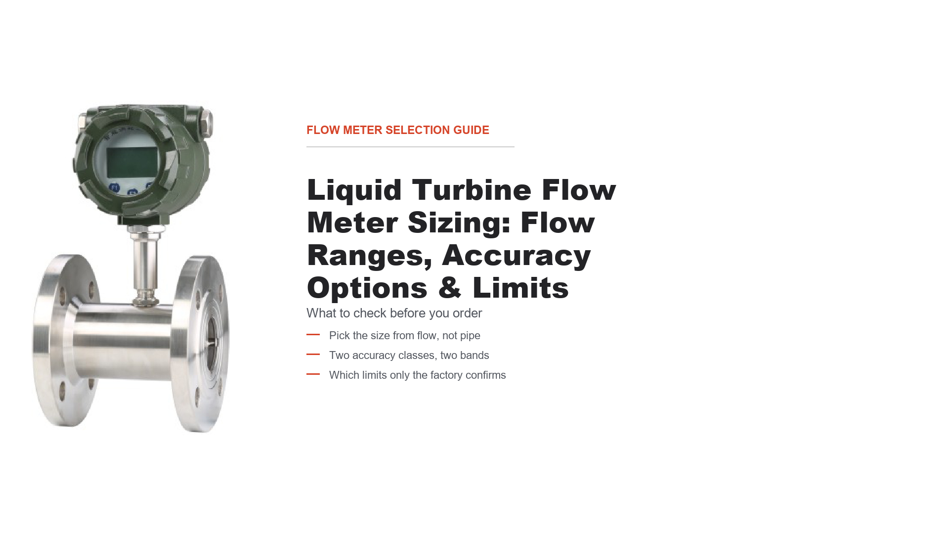
Liquid Turbine Flow Meter Sizing: Flow Ranges, Accuracy Options & Limits
Sizing a liquid turbine flow meter: compare the two published accuracy classes, size on flow not pipe, and know which limits only the factory can confirm.
A turbine flow meter is one of the few flow instruments where the wrong purchase decision is invisible at the moment of purchase. The meter arrives, it fits the flanges, it spins, it outputs a signal. The problem shows up months later, when the numbers do not reconcile with a tank gauge, a batch total or a supplier invoice — and by then the meter has been blamed for something that was decided at the sizing stage.
This guide is about the decision that precedes the order. It works through the LW liquid turbine flow meter, because that is the meter whose published flow table lets you check your own duty against two different accuracy classes. Where the catalog does not answer a question, this guide says so rather than filling the gap with a number.
What the LW catalog does and does not tell you about sizing
Three things are published and directly usable:
- A flow range table by nominal size from DN4 to DN200, with two separate columns — one for the 0.5% accuracy class and one for the 1.0% class.
- Working pressure, maximum pressure loss, medium temperature −20 to +100 °C, and ambient temperature −25 to +55 °C.
- The medium is described as clean, low-viscosity liquid in a closed pipe.
Three things are not published, and they matter to sizing:
- No viscosity limit, in cSt or any other unit. The catalog says "low viscosity", not "up to X cSt".
- No K-factor table, no linearity band, no repeatability figure, and no statement of the accuracy basis — nothing says whether the class is a percentage of reading or of full scale.
- No filtration rating, no straight-run requirement, and no bearing life.
That is the basis for what follows. The first three let this guide be specific; the second three are why several sections end in "confirm with the factory" rather than a number — not evasion, but the difference between a datasheet and an invented one.
The mistake that costs the most: sizing on pipe size
The most common turbine sizing error is to look at the pipe and order the matching meter size. It is intuitive, it is fast, and it is wrong often enough that it is worth naming first.
A turbine meter measures velocity. The rotor turns because the flowing liquid pushes it, and the pulse rate is proportional to how fast the liquid moves through the bore. Flow rate and velocity are linked by cross-sectional area, so a 2-inch meter in a 2-inch line is only correct if the flow happens to sit in that meter's usable band.
When the meter is too large for the duty, the liquid creeps through it. Rotor speed falls, bearing and viscous drag become a larger share of the forces on the rotor, and the relationship between pulses and volume stops being stable. The meter still produces a number. It is simply not the number you are paying for. Independent technical sources converge on the same practical picture — usable accuracy degrades toward the bottom of the range, and sizing on maximum flow alone leaves the meter running near its floor at normal duty. Treat the specific percentages quoted elsewhere as model-specific; the mechanism, not the number, is what transfers.
The practical rule is the opposite of the intuitive one: choose the size from your normal flow, then check that your maximum and minimum both still fit. If they do not, the answer is usually a different size or a different technology, not a meter run outside its band.
Read the two accuracy columns separately
This is the part of the LW table that most repays a careful look, because it is where the catalog is more informative than a typical datasheet.
The flow range for each size is published twice: once for the 0.5% accuracy class and once for the 1.0% class. The two columns are not the same numbers, except at DN6, DN50, DN65 and DN80 where they coincide. In the sizes where they differ, the 0.5% class starts at a higher minimum flow, and the 1.0% class sometimes reaches a higher maximum as well — so the wider class is not always the one you would guess.
The consequence is commercial, not academic: buying the tighter accuracy class can cost you usable range at the bottom end. If your duty spends most of its life at low flow, the 0.5% meter may be the worse choice even though it is the better meter, because your normal operating point may fall outside the band in which that class is offered.
The table below reproduces the published ranges.
DN (mm) | Flow range, 0.5% class (m³/h) | Flow range, 1.0% class (m³/h) |
|---|---|---|
4* | — (not offered) | 0.04–0.25 |
6* | 0.1–0.6 | 0.1–0.6 |
10 | 0.25–1.2 | 0.2–1.2 |
15 | 0.6–4 | 0.4–4 |
20 | 1.1–7 | 0.7–7 |
25 | 1.6–10 | 1–10 |
32 | 2.5–16 | 1.6–16 |
40 | 3–20 | 2.5–25 |
50 | 4–40 | 4–40 |
65 | 6–60 | 6–60 |
80 | 10–100 | 10–100 |
100 | 20–160 | 16–160 |
150 | 50–300 | 40–400 |
200 | 100–600 | 80–800 |
Read the table this way. For DN25, the 0.5% class covers 1.6–10 m³/h while the 1.0% class covers 1–10 m³/h. If your normal flow is 1.2 m³/h, the 1.0% meter is inside its published range and the 0.5% meter is not. For DN150 the two classes differ at both ends: 50–300 against 40–400. At DN40 the 1.0% class is wider on both sides — 2.5–25 m³/h against 3–20 m³/h — so it starts lower and reaches higher.
Two further points on reading it. Sizes marked with an asterisk (DN4 and DN6) carry a note in the catalog that is not legible at the resolution available, so confirm those variants directly with the factory rather than inferring from the table. And the table gives the offered band, not a statement that the accuracy figure holds uniformly across it — see the next section.
The sizing procedure, step by step
This is the sequence that produces a defensible size choice.
Step 1 — Establish the real flow range, not the nominal one. You need three numbers: normal operating flow, the maximum the system can see, and the minimum at which the process still needs a meaningful measurement. The minimum is the one buyers most often fail to define, and it decides the size. If a tank is emptied at a declining rate, the minimum is the trickle at the end, not the average.
Step 2 — Convert everything to one unit and one basis. The LW table is in m³/h. If your duty is in L/min, GPM or kg/h, convert before comparing. For a liquid, mass flow needs a density to become volumetric, and that density must be at the operating temperature — hot oil at 80 °C is meaningfully less dense than the same oil cold, and using the cold figure shifts your volumetric equivalent.
Step 3 — Compare your minimum against the 0.5% column first. If your minimum sits inside the 0.5% range for a size, that size is a candidate at the tighter class. If it does not, try the 1.0% class of the same size, which usually reaches lower. Only if that still misses your minimum should you consider a smaller size — and only if it also covers your maximum, within its pressure loss and installation conditions. Moving to a larger size does not help a minimum-flow problem: a larger bore makes the minimum worse.
Step 4 — Check your maximum against the same size. Both ends must sit inside the same column. A duty of 1.2–9 m³/h fits DN25 at 1.0% (1–10) but not at 0.5% (1.6–10). A duty of 1.2–12 m³/h exceeds DN25 at 1.0% (1–10). DN32 at 1.0% covers the maximum (1.6–16) but its minimum of 1.6 m³/h is above the 1.2 m³/h low end, so DN32 is not a qualified selection. Where no single size and class covers both ends, say so plainly: the duty cannot be met by direct selection, and the answer is to change the process condition, split the range across two meters, or evaluate another technology.
Step 5 — Confirm the accuracy claim covers your points. This is the step the catalog cannot close. The published figure is a class (0.5% or 1.0%), and the table gives the band in which that class is offered. The catalog does not state whether the class is a percentage of reading or of full scale, and does not give tested accuracy at specific points inside the band. Ask for both in writing against your normal and minimum flow before you commit — the gap between the two bases is largest exactly where turbine meters are weakest, and it is a commercial term, not a detail to settle after delivery.
Step 6 — Confirm working pressure and pressure loss for the exact model. Neither can be settled from this guide: the catalog's pressure column uses merged cells that do not map reliably to individual sizes in the available copy, and it carries starred entries whose note is not legible. No pressure rating or pressure-loss figure is reproduced here for selection purposes, and nothing in the starred entries should be read as a capability or commitment. Obtain both for your size and connection from verifiable official documentation or written factory confirmation, and ask for the pressure loss at your actual flow if available head is marginal. Medium temperature is published as −20 to +100 °C and ambient as −25 to +55 °C across the family; confirm those for your model too.
What the meter cannot fix: viscosity, cleanliness, air
Sizing gets the geometry right. These three decide whether the meter keeps reading correctly afterwards, and none can be fixed by choosing a different size.
Viscosity. A turbine meter's calibration is established against a fluid of a particular viscosity. Change the viscosity and the rotor's response changes, because viscous drag on the rotor and in the bearing is part of the force balance. Sources agree on the mechanism and disagree sharply on the numbers — published limits range from about 20 cP to several hundred cSt depending on manufacturer and bearing design. The LW catalog states only "low viscosity" and gives no limit, no K-factor versus viscosity relationship, and no correction curve. So: if your liquid is water-like the question is likely moot; if it is oil, syrup, resin, paint, or anything whose viscosity changes materially with temperature, send the viscosity at operating temperature and at your lowest expected temperature, and let the factory confirm. Do not assume a water-calibrated meter transfers to a viscous duty.
Cleanliness. The catalog specifies clean liquid and lists three sensor variants — standard, wear-resistant and corrosion-resistant. For the wear-resistant variant it states that the shaft and bearing use a hard-alloy material and that the impeller is designed with a small reverse thrust, better suited to liquids with poorer lubricity. That variant exists because turbine meters wear. Particles passing the rotor can erode the bearing; as bearing geometry changes the pulse-per-litre relationship can drift, and field reports commonly describe a meter reading low — though the direction and size of any drift depend on the wear pattern and should not be predicted for a given installation. Independent sources recommend an upstream strainer and identify bearing condition as a significant wear item. The catalog publishes no filtration rating and no bearing life figure. If your liquid is not visibly clean, state the filtration you actually have and ask what the meter requires; a Y-strainer sized for the pump is not automatically sufficient.
Air and vapour. Entrained gas is a serious error source in a liquid turbine meter. Bubbles occupy volume the rotor does not see as liquid, so a meter with air in the stream can over-read, and a large slug can overspeed the rotor. How much the reading shifts depends on how much gas is present and how it is distributed — steady dissolved gas behaves differently from intermittent slugs. Field reports commonly list entrained air among the causes of a meter reading high. Practically: avoid points where air can be drawn in, keep the meter away from pump suction, and where dissolved gas can come out of solution maintain enough back pressure. The catalog gives no back-pressure or air-elimination requirement. Treat recommendations you see elsewhere as generic practice, not as Yuanda's specification.
Where the liquid is dirty, abrasive or contains solids, a turbine meter is often a poor fit because of its moving parts — conductivity is not the deciding factor either way. An electromagnetic meter is a candidate when the medium, its conductivity and the installation conditions all meet that family's requirements, and the electromagnetic flow meter family page is the alternative to compare against.
K-factor and what calibration actually covers
The K-factor is the number that turns pulses into volume: pulses per litre, or pulses per US gallon. It is the single most important number in a turbine meter's calibration, and it is the one most often misunderstood at the purchasing stage.
Three things are worth being clear about before you specify.
A K-factor is established for particular conditions, not for a fluid in the abstract. It is determined against a calibration fluid at stated flow points. If your service fluid differs in viscosity, density or lubricity from the calibration fluid, the K-factor you were given may not transfer directly — but it may also be insensitive over part of the operating range, and how much it moves depends on the meter design and the fluids involved. The LW catalog publishes no K-factor table and no viscosity-versus-K-factor relationship, so whether your duty is affected is a factory question, supported by the calibration certificate.
A K-factor is not perfectly constant across the range. Real turbines have a slight curve: the pulse-per-volume relationship varies a little with flow, which is why linearity is quoted separately from accuracy. The LW catalog does not publish a K-factor table, a linearity figure, or the flow points at which the meter is calibrated. Ask for the K-factor and the linearity band with the certificate, and ask at which flow points the calibration was performed.
"Calibration certificate" is not one thing. Buyers sometimes accept a document that states a K-factor without saying what it is traceable to, what the measurement uncertainty is, or what fluid and temperature were used. A useful certificate states the calibration fluid and its viscosity, the flow points tested, the as-found and as-left values, the measurement uncertainty, and the traceability chain to a national standard. Whether the LW is supplied with such a certificate as standard, and whether calibration at your service viscosity is available, is not stated in the catalog and has to be confirmed.
One further distinction worth knowing, because it appears in supplier discussions: a quality-system certificate (for example an ISO 9001 certificate covering the factory) is not a calibration certificate. They answer different questions and neither substitutes for the other.
Installation conditions that change the reading
Three installation conditions affect whether the meter delivers the accuracy it was sold with. The catalog does not publish figures for any of them, so each is a confirmation item rather than a specification.
Straight run. A turbine meter needs an undisturbed velocity profile. Published guidance from manufacturers varies widely — some state 10 diameters upstream and 5 downstream, others 15 or 20 upstream, with more after a valve, elbow or expansion. The variation is real and manufacturer-specific, which means the only correct number for an LW is the one in Yuanda's installation instructions. Before ordering, measure what your pipework actually offers: count the fittings upstream of the proposed point, not just the straight pipe length. If the available run is short, say so on the enquiry — a flow straightener or a different location may be the answer, but that is a factory discussion.
Orientation and full pipe. Turbine meters are generally installed so the pipe runs full. Air or vapour accumulating at the top of a partially filled line will corrupt the reading. The catalog does not state orientation limits, so confirm the permitted mounting orientation for your model.
Pulsating or fluctuating flow. A reciprocating pump or a fast-acting valve produces a pulsating flow that a turbine meter will integrate differently from a steady flow. The catalog does not address pulsation. If your system has it, describe it.
Common questions before ordering
Can I use a turbine meter on a line that is bigger than the meter? Mechanically yes, with reducers, but the meter then sees a different velocity from the line average. Size the meter from the flow, then design the pipework around it — not the reverse.
My flow varies a lot. Can one turbine meter cover it? Up to a point, and the two accuracy classes have different low ends. If your minimum falls below the 1.0% column for the size that fits your maximum, one meter will not cover the duty well. Splitting the range or changing technology is the honest answer.
Does the meter need temperature compensation? The LW measures volumetric flow. If you need mass or standard volume, you convert downstream using density at the operating temperature. Whether the electronics provide compensation in a given configuration is a model-code question, not something to assume.
Will it work on diesel, oil or a food liquid? That depends on viscosity, lubricity, cleanliness and the materials in contact with the fluid, and none of those limits is published. Send the fluid, its viscosity at operating temperature, and its temperature range, and let the factory confirm — this is where a water-calibrated assumption is most likely to be wrong.
What accuracy will I actually get? The class is 0.5% or 1.0%, published per size and per accuracy column. Not published: whether that figure is a percentage of reading or of full scale, and the tested accuracy at specific flow points. Ask for both against your duty points.
RFQ checklist: what to send, and what to ask
The catalog closes the sizing geometry. This table separates what you can settle from it from what needs the factory.
Information category | What to specify | Why it matters |
|---|---|---|
Fluid | Fluid name; whether it is clean and low-viscosity | The family is specified for clean, low-viscosity liquid |
Viscosity | At operating temperature and at the lowest expected temperature | No limit is published; this is the main suitability question |
Flow range | Minimum, normal and maximum flow, with units | The size comes from the range, not the pipe; the minimum decides it |
Accuracy class | 0.5% or 1.0%, against your actual band | The two classes have different low ends |
Pipe size and connection | Nominal size; flange, thread or clamp | Sizes DN4–DN200; all three connections offered |
Pressure | Line pressure and required rating, for the exact size and connection | Must be confirmed from verifiable official data or in writing by the factory |
Temperature | Medium and ambient temperature | −20 to +100 °C medium, −25 to +55 °C ambient |
Cleanliness | Filtration upstream and particle size, if known | No filtration rating is published; bearing wear is a significant failure mode |
Installation | Straight run, upstream fittings, orientation, pulsation | No straight-run or orientation figures are published |
Air or vapour | Whether entrainment is possible, and available back pressure | Entrained gas can cause over-reading; no requirement is published |
Output | Pulse, 4–20 mA, battery or intelligent; integrated or split | Part of the model code |
Calibration | Certificate content, calibration fluid, viscosity, uncertainty | Not stated in the catalog; agree before ordering |
Accuracy basis | Whether the 0.5% / 1.0% class is a percentage of reading or of full scale, and tested accuracy at your duty points | The catalog states only the class; the basis must be confirmed in writing |
K-factor | Whether it and its linearity band are supplied and marked on the meter | Not published; must match your flow computer |
Hazardous area | Area classification, if applicable | No certification is listed for this family |
The short version for the email: fluid and its viscosity at operating temperature, minimum / normal / maximum flow, the accuracy class you are considering, pipe size and connection, pressure and temperature, upstream filtration, available straight run, and whether air entrainment or pulsation is possible.
Send those and the reply can be a model code rather than a question. If the minimum flow is uncertain, say so and give the range you do know — that number decides the size more than any other, and it is cheaper to settle before the order than after the first reading you cannot explain.
The LW turbine flow meter family page sets out sizes, connections and output options, and the LW flanged turbine flow meter page carries the flanged configuration. If you are still choosing between families rather than a size within this one, start with how to select the right flow meter.
Send your fluid, viscosity, flow range, pipe size, pressure, temperature and installation conditions through the quote request form and we will confirm the size, accuracy class and model code.