Oct 17, 2026Flow Meter Selection Guides
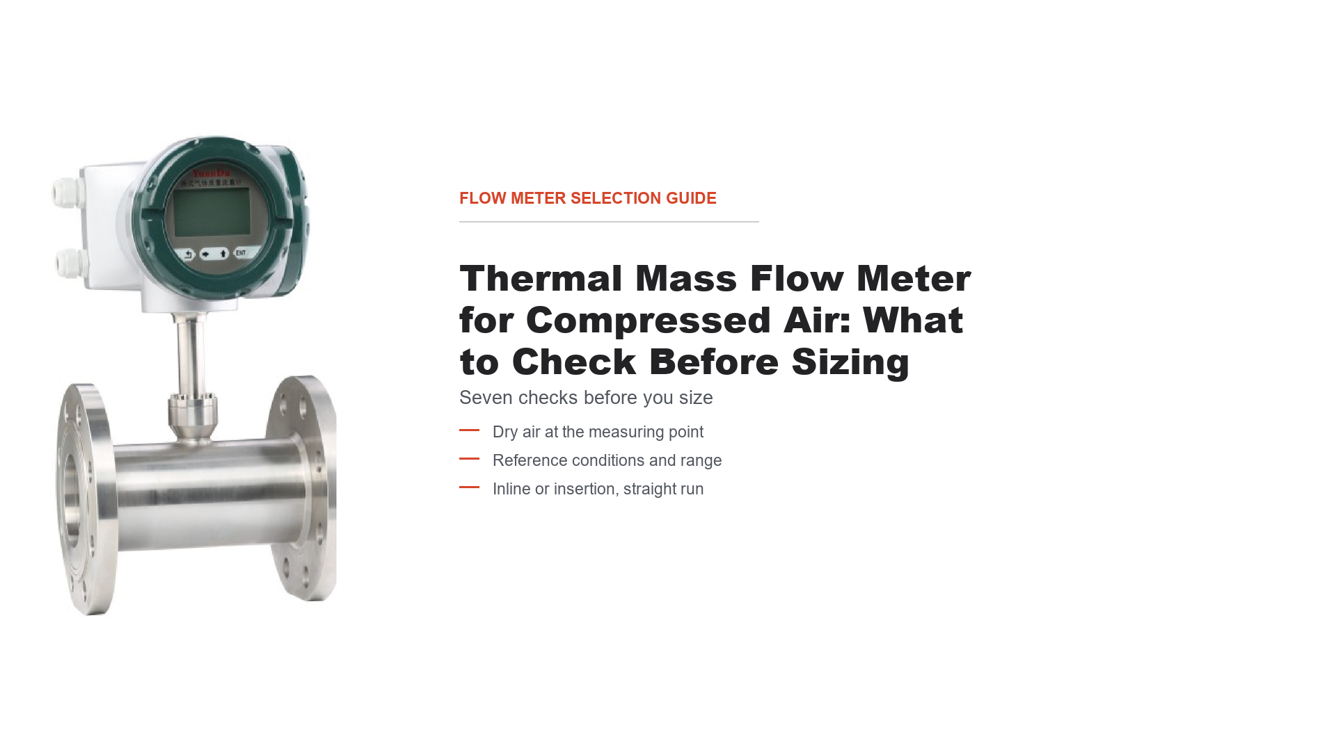
Thermal Mass Flow Meter for Compressed Air: What to Check Before Sizing
Seven checks before sizing a thermal mass flow meter for compressed air: dry air, reference conditions, range, inline or insertion, straight run and outputs.
Compressed air is one of the few utilities where almost every plant measures pressure, run hours and amps, and almost nobody measures the flow. Once a buyer decides to close that gap, the question is rarely "which meter" — it is what must be settled before anyone can quote a number worth trusting.
This guide works through seven checks that decide whether a thermal mass flow meter will suit a compressed-air line, in the order they cause trouble. It is written around the LR thermal gas mass flow meter, because that is the meter whose published air tables you can check your flow against. Where the catalog does not answer a question, this guide says so.
What the LR catalog does and does not claim for compressed air
Three things are stated in the 2024 catalog:
- Air is a listed application gas, alongside oxygen, nitrogen, argon, helium, hydrocarbon gas, natural gas and coal gas.
- The published flow selection tables are stated to apply to air, oxygen and other near-ideal gases.
- The medium specification is a single-component gas, or a composition-stable dry mixed gas, excluding acetylene and hydrogen.
The first two are why the air tables are useful: the ranges were built for air, not converted to it afterwards. The third is why dryness is the first check here rather than a footnote.
What the catalog does not state is a maximum water content, an oil-carryover limit, a wet-air service rating, a cleaning procedure for a fouled sensor, or any behaviour under pulsating flow. Nothing below should be read as confirming them.
That is also the boundary on "compressed air" itself: the meter is specified for dry gas and its tables are air-based, which is not a commitment that every compressed-air installation is suitable.
Check 1: is the air dry where you plan to measure it?
The medium specification says dry gas. Compressed air is only as dry as the installation makes it, and where you tap the line influences that more than the meter does.
Air leaves a compressor warm, and its ability to hold water vapour falls as it cools through the aftercooler and pipework. Some of that water is removed at separators, filters and dryers, and how much remains at any point depends on the dryer type, its condition, the line temperature and the flow. A header is therefore not uniformly wet or dry: assess the moisture condition at the point you intend to use, not from the presence of a dryer upstream.
Where liquid water reaches a heated thermal sensor, evaporation draws heat from the sensor in addition to the heat carried off by the gas, and the indicated flow can read higher than the true value. How large that effect is depends on how much liquid is present, how it is distributed, and the meter's design. The concern is not that any moisture destroys the reading, but that condensate makes it unreliable in a way that is hard to detect afterwards.
The sound placement is a section of line that is dry in normal operation, downstream of the drying and filtration stages, and still representative of the flow you need to measure. If the point you need sits upstream of the dryer — to catch a dryer fault, or to meter an individual compressor — that is legitimate, but a different requirement, and the selection has to be revisited.
Compressor oil that reaches the sensor can coat it, and the catalog gives no cleaning interval or service procedure, so if your air is not oil-free, put the filter condition and the oil class on the enquiry. Note too that if you meter downstream of a desiccant dryer to build a system total, the dryer's purge flow may leave before your meter — the meter is not wrong, the boundary of what you are metering is.
The moisture and contamination limits are not published. The catalog requires dry gas but states no maximum water content, no oil-carryover tolerance and no wet-air service rating. Those are factory questions for your specific point, and this guide does not substitute a number for them.
If your air is genuinely wet at the only usable point, do not solve that by choosing a different thermal meter. Move the point, dry the air, or use a technology intended for wet gas.
Check 2: mass flow, standard volume, or actual volume?
Three different numbers get called "the flow" on a compressed-air line, and they are not interchangeable.
Actual volume is the volume the air occupies at the pressure and temperature in the pipe right now. It is what a velocity-based device senses, and the same mass occupies less of it as pressure rises.
Mass flow is kilograms per hour — how much air is passing, not how much space it fills, so it needs no pressure correction to be meaningful. This is not a claim that pressure never affects the reading: if line pressure changes because the system is genuinely moving more or less air, mass flow changes too. What pressure does not do is change the number on its own, the way it changes an actual-volume figure.
Standard volume is that mass expressed as a volume at a defined reference condition. It is a reporting convention, not a physical measurement, and it is what most compressed-air reporting means by "normal cubic metres". Because the reference is fixed, a standard-volume number tracks mass, not line pressure.
The distinction that catches people is between a physical change in flow and a change of reporting unit. The same mass reported as actual volume at line pressure and as standard volume gives two numbers differing by the pressure ratio; neither is wrong, they answer different questions. If you raise the pressure and the compressor delivers correspondingly more air, that is a real increase in mass flow and shows up in both.
The LR measures mass flow directly by the constant-temperature-difference method: one sensor measures gas temperature, a second is heated above it, and the heat carried away by the flowing gas is a function of mass flow. Because the sensor pair works on mass and heat transfer, arriving at a mass figure needs no external temperature and pressure correction.
The LR's displayed and totalised value is standard volume, not kilograms. The catalog lists standard-condition instantaneous flow, cumulative flow and standard velocity — all at 20 °C and 101.325 kPa.
Two consequences follow. If you report in kg/h you convert: at 20 °C and 101.325 kPa dry air is about 1.20 kg/m³, so 1 Nm³/h is roughly 1.20 kg/h — an approximation, not a calibration constant. And if you compare this meter against an instrument reporting actual volume, or a compressor datasheet quoting free air delivery, you are comparing different bases.
For leak detection and system efficiency, standard volume or mass is the right basis, because both ignore the pressure fluctuations you are trying to see past.
Check 3: which reference condition is the number on?
"Standard" is not one condition, and this check quietly costs people a few percent.
Different industries and instruments anchor it differently — commonly 0 °C, 15.6 °C (60 °F), 20 °C or 25 °C, at 101.325 kPa, 100 kPa or 14.696 psia. For the LR the catalog states it explicitly as 20 °C and 101.325 kPa, the basis for every number in the flow tables.
The trap is comparing across bases. A reading on a 20 °C basis and one on a 0 °C basis describe the same physical amount of air but differ by about 7.3%, because the gas occupies a different volume at a different temperature. That gap is larger than the accuracy figure most meters are sold on.
Target basis | Temperature | Pressure | Multiply the LR reading by |
|---|---|---|---|
LR standard (Nm³/h) | 20 °C | 101.325 kPa | 1.000 |
Nm³/h referred to 0 °C | 0 °C | 101.325 kPa | 0.932 |
SCFM at 68 °F | 20 °C | 14.696 psia | 0.589 |
SCFM at 60 °F | 15.6 °C | 14.7 psia | 0.580 |
Volume at 1 bar rather than 101.325 kPa | 20 °C | 100 kPa | 1.013 |
These multipliers assume the gas stays at the stated temperature and that air behaves closely enough to an ideal gas over the range in question. They convert the same mass; they are not measurements.
Worked example: 100 Nm³/h on the LR's 20 °C basis is 93.2 Nm³/h restated at 0 °C, 58.9 SCFM at 68 °F, or 58.0 SCFM at 60 °F. Same air, five ways of writing it.
Absolute or gauge? The 101.325 kPa in the standard condition is absolute. Line pressure on a plant is normally quoted as gauge. Using the wrong one is not a rounding error: a line quoted at 0.7 MPa is 700 kPa absolute if that figure was absolute, but 801.325 kPa absolute if it was gauge. At constant temperature, treating air as an ideal gas, the standard-to-actual volume factor is 0.145 in the first case and 0.126 in the second — a 15% difference in the number you get. State which one your figure is, in the enquiry.
Three consequences follow. When you compare quotes, compare bases — a vendor quoting SCFM and one quoting Nm³/h are not necessarily quoting the same flow. When you compare against a compressor datasheet, check the basis of the free air delivery figure. And when you set a leak-reduction baseline, fix that basis in writing.
Check 4: does your flow range fit the published air table?
The LR family covers DN25 to DN2000 across three connection styles: flange DN25–150, thread DN25–50 and insertion DN125–2000. Flow tables are published separately for the flanged and insertion versions, in Nm³/h at 20 °C and 101.325 kPa. Key rows follow; the catalog lists an insertion value for every size from DN125 to DN2000.
DN | Flange min (Nm³/h) | Flange max (Nm³/h) | Insertion min (Nm³/h) | Insertion max (Nm³/h) |
|---|---|---|---|---|
25 | 1 | 100 | — | — |
50 | 4 | 400 | — | — |
65 | 6.5 | 650 | — | — |
80 | 10 | 1000 | — | — |
100 | 15 | 1500 | — | — |
125 | 25 | 2500 | 25 | 2500 |
150 | 35 | 3500 | 35 | 3500 |
200 | — | — | 65 | 6500 |
300 | — | — | 150 | 15000 |
500 | — | — | 400 | 40000 |
800 | — | — | 1000 | 100000 |
1000 | — | — | 1600 | 160000 |
1500 | — | — | 3560 | 356000 |
2000 | — | — | 6350 | 635000 |
Two notes on reading it. The stated range applies to air, oxygen and other near-ideal gases; for other gases it changes and has to be agreed at the enquiry. Maximum flow can be extended on the velocity side to 100 Nm/s by arrangement, a commercial option rather than a standard line item.
The velocity band. Medium velocity is given as 0.56 to 56 Nm/s standard, extended to 100 Nm/s. Those are velocities at standard conditions, consistent with the Nm³/h basis — not actual velocity in the pipe. At 0.7 MPa gauge the actual velocity in the same pipe is about eight times lower (56 Nm/s becomes roughly 7 m/s), because the air is denser. Check that any velocity figure you compare against shares the same basis.
The band also gives a rough cross-check on a flow figure you have been handed. For air at standard conditions:
Q (Nm³/h) ≈ 2827 × V (Nm/s) × D² (m²)
Here D is the actual internal diameter in metres, not the nominal size. DN is nominal and the bore varies with schedule and wall thickness, so substituting DN directly introduces error — modest at small sizes, larger where the wall is thick relative to the bore. Use the measured or specified bore when it matters.
As an illustration only: a 100 mm bore at 56 Nm/s gives about 1580 Nm³/h, close to the 1500 Nm³/h table maximum for that size. This is a plausibility check, not a sizing calculation; the rating has to come from the factory against your actual bore, pressure and temperature.
On turndown. The catalog describes a range ratio above 100:1 and notes suitability for leak detection. It does not give the measurement uncertainty at the bottom of the span, which decides whether the low end of your range is real.
Check 5: inline or insertion?
The family offers both, and the choice turns on pipe size, installation method and what the site can accommodate.
A flanged meter is a spool piece: the full flow passes through the body, so it needs a line break and matching flanges, and it measures the whole cross-section. An insertion meter mounts through a tapping and puts a probe into the existing pipe, so it can be fitted to a line already built. Its measurement is taken at one point, so the result depends on the flow profile being what the installation assumes.
Coverage decides many cases by itself. Flange runs DN25–150, insertion runs DN125–2000, and only DN125–150 offers both. Below DN125 the flanged version is what is offered; above DN150 the insertion version is. In the overlap the decision rests on installation method and site conditions rather than on range.
What is not confirmed. The insertion drawing shows a ball valve and a double-ferrule fitting on the probe assembly, but the catalog does not state that the meter can be installed, removed or serviced against a live, pressurised line. A valve in a drawing is not a statement of hot-tap capability. Whether the LR supports wet tapping, and how the probe is inserted and withdrawn in service, has to come from the factory for your model and line. Do not plan a shutdown-free installation on the strength of the drawing.
Check 6: will the straight run fit?
The catalog states the requirement as at least 20DN upstream and 10DN downstream, noting that 90° elbows and pipe expansions need more, per the manual. Twenty diameters is easy to agree to on paper and hard to find in a compressor room, so convert it before committing:
DN | 20DN upstream | 10DN downstream |
|---|---|---|
50 | 1.0 m | 0.5 m |
80 | 1.6 m | 0.8 m |
100 | 2.0 m | 1.0 m |
150 | 3.0 m | 1.5 m |
200 | 4.0 m | 2.0 m |
300 | 6.0 m | 3.0 m |
500 | 10.0 m | 5.0 m |
On a DN500 header that is ten metres of clear pipe upstream. This is the check that most often changes a project, so walk the route with a tape measure before the enquiry.
Two things to plan for. The 20DN must be the right 20DN: pipe immediately after a valve, a reducer or a compressor discharge is still pipe, but the profile through it is disturbed, and the catalog defers exact allowances to the manual — so describe what is physically upstream when you enquire. Insertion also carries a profile assumption: the measuring point is pipe centre for DN125–300 and the mean-velocity point at 0.121D from the wall for larger sizes.
If the straight run cannot be found, the options are to move the point, to accept a reduced accuracy claim, or to choose a technology that tolerates a poorer profile — not to shorten the requirement silently.
Check 7: temperature, pressure and output — read the model code
This group is readable from the model code, which makes it the easiest to close.
Temperature. Two medium-temperature variants exist: −10 to +100 °C and −10 to +200 °C, encoded as 3 and 3G. Ambient temperature is −20 to +45 °C. Air downstream of a dryer usually sits inside the first range; the second exists for hot gas lines and points near a compressor discharge. Pick from the temperature at the point, not the discharge temperature.
Pressure. The standard rating is stated as 1.6 MPa. Higher ratings of 2.5 and 4.0 MPa are listed for flanged meters DN25–DN100. That limit is real: a DN150 flanged line at 2.5 MPa, or any insertion meter above 1.6 MPa, falls outside the model code and has to be discussed with the factory.
The 1.6 MPa figure is not settled across the two catalog pages. The technical data table gives 1.6 MPa as standard across flanged DN25–150 and lists the thread version at 1.6 MPa; the model code gives 1.6 MPa for flanged DN25–100 and marks the thread version at 1.6 MPa as a special build. The pages disagree on both the flange upper size and whether the thread version at 1.6 MPa is standard or special. Treat 1.6 MPa as the published standard figure pending confirmation, not a confirmed rating for every size and connection. Confirm it in writing for the exact size and connection you order.
Accuracy. The catalog states
±(1.5+0.5FS)%. The page does not define FS, and does not say whether the 1.5 is a percentage of reading or of full scale, so two readings are possible. This guide does not reinterpret it or convert it into a plain accuracy figure. Ask for the accuracy statement in the form your project requires — ideally tested points across your range — and establish whether the 0.5 FS term is additive to a reading-based figure.Outputs. The technical data lists four signal types: 4–20 mA with a maximum load of 500 Ω, pulse, RS485, and HART. The standard configuration code specifies the 4–20 mA output, upper and lower limit alarms, RS-485 Modbus RTU, and an LCD showing instantaneous and cumulative flow, velocity, output current and alarms. Pulse and HART appear in the technical data but not in that standard configuration list, so if you need either, confirm how it is configured. Alarm contacts are 1–2 relays rated 10 A/220 VAC and 5 A/30 VDC. Power is DC24 V or AC220 V at 18 W or less; enclosure IP65.Hazardous area. A model-code entry is listed as
Bd: Ex d IIC T6 Gb. That is the catalog's marking, and it is all this guide can tell you: no certificate, certificate number, notified body or temperature-class basis accompanies it. If your installation needs hazardous-area approval, ask the factory for the valid certificate covering the exact model, size and connection you order, and check it against your own area classification before purchase. Do not treat the marking as evidence of a certification in hand.For a monitoring project the output choice comes down to whether the meter feeds a PLC or building management system (4–20 mA or Modbus) or a datalogger for an energy study (pulse for totalising). If you need Modbus, ask for the register map; the catalog gives the protocol but not the map.
Body. The body is 304 or 316 stainless steel, with 316 listed for flanged and threaded versions. Flanged face-to-face length is 200 mm for DN25–50 and 220 mm for DN65–150.
Common questions before sizing
I need 500 Nm³/h at 0.7 MPa. Which size? The tables are in Nm³/h at standard conditions, so the line pressure does not enter the flow-table lookup. A DN65 flanged meter covers up to 650 Nm³/h and a DN80 up to 1000 Nm³/h, so either brackets 500 Nm³/h. The choice comes down to the low end of your range, the straight run, and confirmation of the pressure rating for that exact size — see Check 7 on the 1.6 MPa conflict.
What accuracy should I expect at the low end of the range? The catalog gives
±(1.5+0.5FS)% without defining FS or stating whether the fixed term is reading or full-scale based. That ambiguity matters most at low flow, where any fixed term has its greatest relative effect. Ask the factory for tested accuracy at your minimum flow rather than scaling the headline figure yourself.RFQ checklist: what to send, and what to ask
The catalog closes most sizing questions. This table separates what you can decide from what only the factory can confirm.
Information category | What to specify | Why it matters / source |
|---|---|---|
Gas and dryness | Gas composition; whether the air is dry, and where the point sits relative to the dryer | Confirms the medium is within specification; no water limit stated |
Oil carryover and filtration | Oil class and filter condition, if the air is not oil-free | Affects fouling and service life; no cleaning procedure published |
Flow range and basis | Minimum and maximum flow, with units, and the reference condition you report in | Sized against the air table; prevents baseline mismatch |
Pipe size and connection | Nominal size; flange, thread or insertion | Flange DN25–150, thread DN25–50, insertion DN125–2000 |
Straight run | Upstream and downstream fittings, not just pipe length | 20DN / 10DN required; extra for elbows and expansions |
Pressure | Line pressure as gauge or absolute; required rating, and the size/connection it applies to | 1.6 MPa is the published standard but the two pages disagree; 2.5 / 4.0 MPa only flanged DN25–100. Confirm in writing for your size |
Temperature | Medium temperature at the point and the required variant | 100 °C or 200 °C version |
Output and protocol | 4–20 mA, pulse, RS485 Modbus RTU or HART; register map if Modbus | Map is not published; pulse and HART are not in the standard configuration |
Calibration and accuracy | Calibration gas and certificate basis; tested accuracy at your minimum flow | Air-equivalent calibration described; FS undefined in the catalog |
Special conditions | Hot-tap or wet-tap need, pulsating flow, hazardous area | Insertion method, pulsating flow and an Ex certificate are all factory confirmations |
Send those and the reply can be a configuration rather than a question. If the moisture condition at your measuring point is not settled, say so — it is the item most likely to change the recommendation, and cheaper to settle before the order than after.
The thermal mass flow meter family page describes the flanged, threaded and insertion versions and their published tables, and the flanged specification is on the LR flanged thermal mass flow meter page. If you are still choosing a family rather than a size within this one, start with how to select the right flow meter. Where the medium is steam rather than air, the compensation question differs and is covered in the vortex flow meter for steam guide.
Send your gas, flow range, pipe size, pressure, temperature and moisture condition through the quote request form and we will confirm whether the LR fits the point and which configuration to quote.