Oct 18, 2026Flow Meter Selection Guides
Acrylic Rotameter for RO Systems: Flow Range, Scale and Mounting
Choosing an LZT acrylic rotameter for RO water treatment: match the measurement point, confirm the liquid or gas scale, and pick panel or inline mounting.
An acrylic rotameter is a simple way to put a real flow number in front of an operator on a reverse-osmosis skid. It is also one of the easiest meters to order wrongly, because the same cast-acrylic body is built with completely different scales depending on what it is meant to measure, and because the specification tables do not publish the one number that decides whether a given RO point is safe to use it on.
This guide works through the decision in the order that prevents the expensive mistakes: which measurement point first, then which scale, then which mount, then which model covers your flow range. It is written around the LZT acrylic rotameter, because that is the family whose tables let you check a real duty against a real model. Where the catalog is silent, this guide says so.
What the LZT catalog does and does not tell you
Three things are published and are directly usable:
- Flow ranges per model, separately for liquid and for gas, in a different set of units for each sub-series.
- Connection and mounting type for every model. Panel-mount models use a quick-connect fitting on the LZT-4T, an internal ZG thread on the LZT-6T and LZT-8T, and an external ZG thread on the larger LZT-15/20/25/40 and the LZT-15L/20L/25L, so a panel meter is not restricted to one thread arrangement. Inline models use internal thread, with external thread also offered on the larger sizes.
- Interface and O-ring material options, with the standard configuration marked in each table.
Three things are not published anywhere in the LZT pages:
- No working pressure rating.
- No medium temperature range.
- No chemical-compatibility statement.
That last group is the reason this guide is careful about RO. An acrylic rotameter is genuinely used on RO equipment — you will find them on the permeate line of packaged systems — but "used on RO" is not the same as "suitable for any pressure in an RO system". The catalog does not give you a pressure figure to check against, so that check has to come from the factory, in writing, for your specific model. This guide will not invent a number to fill the gap.
Choose the measurement point before the meter
The first decision is not the meter. It is where on the RO system the meter will sit, because that determines everything else.
A reverse-osmosis system has several hydraulically different points, and their pressures are not determined by their name:
- Feed water. Before the high-pressure pump the line is at supply pressure, which on a municipal or boosted feed may be only a few bar. After the high-pressure pump it is at the pressure the pump develops against the membranes, which is the highest-pressure part of the system. "Feed water" therefore covers two very different pressures, and the pump is the dividing line.
- Permeate (product water). Usually close to atmospheric, but not universally — a system with a permeate back-pressure valve, a long product line, or a second-stage arrangement can hold permeate at a meaningful pressure.
- Concentrate (reject). On the feed side of the membrane it is at membrane pressure. On the atmospheric side of a reject valve it is not. Where you tap the concentrate line matters as much as which line it is.
- Post-treatment and distribution. Depends on the downstream pump, the storage arrangement and the distribution pressure — not automatically low.
- CIP and chemical dosing. Pressure varies with the CIP pump, and the chemistry is aggressive by design.
The point is that no measurement point can be classified as safe from its label alone. Each one needs its own pressure and temperature established from the actual system drawing.
That is why this guide does not divide RO into "low-pressure points where acrylic is fine" and "high-pressure points where it is not". The catalog publishes no pressure rating at all, so no point on the system can be cleared on the basis of being relatively low. Every measurement point needs its pressure, its temperature and its fluid confirmed against the specific LZT model before anyone selects it.
What the catalog does let you do is settle the other half of the question — the flow range and the scale — which is why those come next.
The consequence for the enquiry is concrete: state the measurement point and the line pressure at that point. A supplier who knows the point can tell you whether acrylic is appropriate at all; a supplier who is only told "1 GPM" cannot.
Liquid and gas scales are separate products
This is the single most common ordering error in this family, and the catalog makes it visible once you know where to look.
Every LZT range table is split into a liquid column and a gas column, and the same model number appears with different numbers in each. That is not a presentation choice — a rotameter scale is established for a fluid, and the float position that reads 5 L/min in air is not the float position that reads 5 L/min in water.
Independent technical guidance on variable-area meters states the same rule directly: the scales on the meter are calibrated for the media type, so an air-calibrated meter is not suitable for water service, and the reverse also fails. The scale spacing differs because the two fluids have very different densities and viscosities.
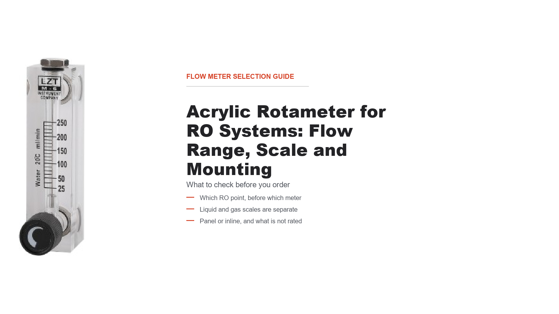
The catalog's own drawings make the same point. On page 04 the LZT-4T dimensional drawing carries a tube labelled "air 20℃ L/min" — a gas scale — while the product photograph on the same page shows a tube marked "Water 20℃ ml/min" — a liquid scale. Both appear in the same panel-meter section. The catalog is not illustrating one universal meter with one universal scale; it is illustrating specific builds, each carrying the scale its fluid requires.
Two cautions about reading these images. First, the scale marking tells you the fluid and reference temperature the numbers are based on; it is not a statement that 20 °C is the meter's operating limit — the catalog publishes no medium temperature range at all, which is a later section. Second, an unlabelled photo in a catalog is not a specification. The page-04 photograph carries no model caption tying it to a specific row in the range table, and its printed numbers do not correspond to any single listed range for a named model. Treat the tube markings as evidence that liquid and gas scales exist side by side — which is the point being made — not as a model-to-range specification.
The catalog's own units make the point:
Sub-series | Liquid range units | Gas range units |
|---|---|---|
LZT-4T | ml/min | L/min |
LZT-6T | LPH (and one GPH range) | L/min |
LZT-8T | LPH | m³/h |
LZT-15 | GPM and LPM | m³/h and L/min (both appear in the gas column) |
LZT-20 / 25 / 40 | GPM and LPM | m³/h |
LZT-15G / 20G / 25G / 40G / 50G / 75G | GPM and LPM (plus LPH rows on LZT-15G) | m³/h |
LZT-15GL / 20GL / 25GL / 40GL | GPM and LPM (plus LPH rows on LZT-15GL) | Nm³/h |
Two things follow.
First, "LZT-15, 1–10" does not specify a product. It specifies a body size and a number. Which scale that number belongs to — liquid or gas, and in which unit — decides what you receive.
Second, the unit narrows the field but does not by itself identify the medium. L/min appears in this catalog as a gas unit on the LZT-4T and LZT-6T, and also in the LZT-15 gas column as an alternative to m³/h — so L/min is not a reliable signal on its own, and it is not reserved to one medium across the family. What identifies the product is the combination: model, calibrated medium, complete flow range, unit, and any reference conditions attached to that range. A specification missing any of those is incomplete, and the catalog alone will not always close it — Nm³/h is printed for the GL group without a stated reference temperature and pressure, so the basis of those normal-volume figures has to be confirmed rather than assumed.
For RO work the practical rule is narrower: permeate and concentrate flows are liquid, so you need a liquid-configured meter and a liquid scale. A gas scale on an RO water line is not a range error — it is the wrong meter.
Panel mount or inline
Once the point and the scale are settled, the mounting decides the sub-series.
Panel mount means the meter sits in a cut-out on a control panel or skid face, with the tube visible to the operator and the connections behind the panel. This is the usual choice for RO equipment because the flows are read by an operator walking past the skid, and because the panel already exists. The catalog has five panel-mount groups:
- LZT-4T — very low flows, quick-connect fitting.
- LZT-6T — low flows, internal ZG1/4" interface, optional adjusting valve.
- LZT-8T — a third set of low-flow ranges in the same internal ZG1/4" interface; its liquid ranges are listed in LPH and its gas ranges in m³/h, so it is not simply a scaled-up 6T. Compare the two tables rather than assuming one is larger.
- LZT-15 / 20 / 25 / 40 — the larger panel sizes, external ZG thread from ZG1/2" up to ZG1½" (LZT-40 also offered in external NPT1½").
- LZT-15L / 20L / 25L — panel versions with a different fixing arrangement, external ZG or NPT.
Inline means the meter is a pipe component, with the tube in the run and the connections at each end. This suits a line that is already piped and has no panel to mount on. The catalog has two inline groups:
- LZT-15G / 20G / 25G / 40G / 50G / 75G — internal ZG thread, with external thread on the larger sizes; nominal sizes DN15 to DN75.
- LZT-15GL / 20GL / 25GL / 40GL — internal or external ZG, DN15 to DN40.
The practical difference for an RO skid is installation, not measurement. A panel meter needs a cut-out and access behind the panel; an inline meter needs the pipe run broken. If the skid is already designed, the panel version usually wins; if you are adding indication to an existing line, the inline version avoids reworking the panel.
One thing the catalog does not do is tell you the panel cut-out dimensions for every variant — the dimension tables give body dimensions (A, B, C…) and thread sizes, not cut-out drawings. If the panel is already cut, confirm the cut-out against the drawing before ordering.
Which model covers your flow — panel-mount ranges
The table below reproduces the published liquid and gas ranges for selected panel-mount models — the LZT-4T, 6T, 8T, 15, 20, 25 and 40. It is not the complete panel-mount range: the LZT-15L, LZT-20L and LZT-25L are also panel meters, and their ranges are published on a separate catalog page and are not repeated here. Those models do exist and can be quoted; check their own table before concluding that a duty has no panel-mount option. Units differ by group, exactly as the catalog prints them.
Model | Liquid range | Gas range | Connection |
|---|---|---|---|
LZT-4T | 6–60, 8–80, 10–100, 40–400 ml/min | 0.1–1, 0.25–2.5, 0.6–6, 1–4, 1–10, 1–12 L/min | Quick-connect |
LZT-6T | 2–20, 4–40, 6–60, 10–100 LPH; 10–70 GPH | 0.1–1, 0.25–2.5, 0.6–6, 1–12, 3–30, 5–50, 10–100 L/min | Internal ZG1/4" |
LZT-8T | 2.5–25, 5–45, 6–60 LPH | 0.1–1, 0.16–1.6, 0.2–2 m³/h | Internal ZG1/4" |
LZT-15 | 0.05–0.5, 0.1–1, 0.2–2, 0.3–3, 0.5–5 GPM; 0.2–2, 0.5–4, 1–7, 1–11, 2–18, 5–35 LPM | 0.1–1 to 4–40 m³/h (multiple); LPM gas ranges also listed | External ZG1/2", internal ZG1/4" |
LZT-20 | 1–10, 2–16, 2–14 GPM; 5–35, 4–60, 12–52 LPM | 2.5–25, 3–30, 4–40, 6–60, 10–100 m³/h | External ZG3/4" |
LZT-25 | 1–10 to 5–45 GPM; 5–35 to 20–170 LPM | 2.5–25 to 30–300 m³/h | External ZG1" |
LZT-40 | 4–40, 10–60, 10–80, 10–80, 10–100 GPM; 15–150, 25–250, 30–300, 50–300, 50–350 LPM | No gas values printed for this size | External ZG1½", external NPT1½" |
Read it this way. If your permeate runs at 1.5 GPM with excursions to 2 GPM, you are looking for a liquid GPM range that brackets both ends. Two panel models do: LZT-15 at 0.5–5 GPM and LZT-20 at 1–10 GPM. Both bracket 1.5–2 GPM, so the choice turns on where your normal flow sits within the range and which connection your panel uses — not on the size of the number alone. Note that 1.5 GPM is not 1.5 LPM: reading the unit correctly is what tells you which table to be in.
That preference for mid-scale operation is engineering judgement, not a catalog rule: the catalog publishes no accuracy-versus-position curve, and ±4% is a single class across the table. Ask the factory to confirm the range that best suits your normal flow rather than relying on the float position alone.
Which model covers your flow — inline ranges
Model | Liquid range | Gas range | Connection |
|---|---|---|---|
LZT-15G | 0.05–0.5, 0.1–1, 0.2–2, 0.3–3, 0.5–5 GPM; 0.2–2, 0.5–4, 1–7, 1–11, 2–18 LPM (plus 10–100, 16–160, 25–250 LPH) | 0.3–3, 0.4–4, 0.6–6, 1–10, 1.6–16, 2.5–25, 4–40 m³/h | Internal ZG1/2" |
LZT-20G | 1–10, 2–16, 2–20 GPM; 5–35, 10–60, 10–70 LPM | 6–60, 10–100, 15–140 m³/h | Internal ZG3/4" |
LZT-25G | 1–10, 2–16, 2–20, 2–25, 3–30, 4–40, 5–45 GPM; 5–35, 10–60, 10–70, 10–100, 12–120, 15–150, 20–170 LPM | 6–60, 10–100, 15–140, 16–160, 25–250, 30–300 m³/h | Internal ZG1" |
LZT-40G | 4–40, 5–45, 6–60, 8–80, 10–100 GPM; 15–150, 20–170, 20–220, 30–300, 40–400 LPM | 35–350, 150–400, 150–500, 120–600, 150–700 m³/h | External ZG1½", internal ZG1½" |
LZT-50G | 20–80, 20–100, 40–120, 50–150, 50–200 GPM; 50–300, 75–400, 150–450, 150–600, 200–800 LPM | 120–600, 300–850, 400–1200, 500–1400 m³/h | Internal ZG2", external ZG2" |
LZT-75G | 50–300, 50–400 GPM; 200–1000, 200–1500 LPM | No gas values printed for this size | Internal ZG3", external ZG3" |
LZT-15GL | 0.05–0.5, 0.1–1, 0.2–2, 0.3–3, 0.5–5 GPM; 0.2–2, 0.5–4, 1–7, 1–11, 2–18 LPM (plus 10–100, 16–160, 25–150 LPH) | 0.1–1, 0.3–3, 0.6–6, 1–10, 1.6–16, 2.5–25, 4–40 Nm³/h | Internal ZG1/2" |
LZT-20GL | 1–10, 2–16, 2–20 GPM; 5–35, 10–60, 10–70 LPM | 6–60, 10–100, 15–140 Nm³/h | Internal ZG3/4" |
LZT-25GL | 1–10, 2–16, 2–20, 3–30, 4–40, 5–45 GPM; 5–35, 10–60, 10–70, 12–120, 15–150, 20–170 LPM | 6–60, 10–100, 15–140, 16–160, 25–250, 30–300 Nm³/h | Internal ZG1" |
LZT-40GL | 1–10, 2–16, 2–20, 3–30, 4–40, 5–45, 6–60 GPM; 5–35, 10–60, 10–70, 12–120, 15–150, 20–170, 20–220 LPM | 6–60, 10–100, 15–140, 16–160, 25–250, 30–300, 35–350, 40–400, 50–500 Nm³/h | External ZG1½", internal ZG1½" |
Note the G/GL distinction: the two inline groups cover overlapping sizes but are listed separately with their own ranges, and the GL group prints gas in Nm³/h rather than m³/h. Do not mix the two tables when specifying. The catalog does not state the reference temperature and pressure behind those Nm³/h figures, so if a gas duty is involved, that basis is a factory confirmation item rather than something to assume.
One more detail, recorded here because it is easy to "correct" by mistake: the two groups are not the same product with a suffix. For example, LZT-15G lists 25–250 LPH in its liquid column while LZT-15GL lists 25–150 LPH. Those are different published ranges for different models and should be quoted as they stand, not harmonised.
For RO permeate duties the relevant inline sizes are usually the small end — DN15 to DN25 — because permeate flows on packaged systems are often modest. Larger inline sizes are more relevant to feed and concentrate lines; whichever line you use, the pressure rating question is the same, because none is published.
What the catalog does not rate: pressure, temperature, materials
Three specification gaps shape every RO enquiry, and they are worth stating plainly rather than working around.
Working pressure. No LZT page publishes a pressure rating. This is not an oversight in reading — the LZS plastic-tube pages in the same catalog do publish one (0–60 °C, ≤0.6 MPa), which shows the catalog does rate its other plastic-tube family. The LZT tables simply do not carry the column. Consequence: there is no point in an RO system that can be cleared for acrylic by inspection. Whether your point is before the pump, after it, on the permeate, or on a distribution line, state the pressure at that point and get written confirmation for the specific model.
Temperature. No LZT medium-temperature range is published. The only temperature figure in the LZT section belongs to the alarm switch option, which is rated 0 to +55 °C — that is the switch, not the meter body, and it should not be read as the meter's rating. If your permeate runs warm, or if the skid is in an uncooled plant room, put the temperature on the enquiry.
Materials and compatibility. The catalog publishes the interface and O-ring options (PVC, PP, ABS, brass, chrome-plated brass, stainless steel; silicone, fluoro rubber, NBR) and marks which is standard. It does not publish a chemical-compatibility table, and it does not state the float material per model. Acrylic has known sensitivities to certain solvents and to strong alkalis — that is general material knowledge, not a Yuanda statement — so for CIP lines, chemical dosing or any non-neutral water, the material question has to go to the factory rather than be inferred from the fitting material.
One further point on acrylic generally, offered as engineering context rather than a Yuanda specification: acrylic is a rigid, transparent thermoplastic that can craze or crack under some solvent exposure and under mechanical stress concentrations. That is why the mounting and the fluid chemistry both matter more than they would on a metal-tube meter. It is also why the working pressure, temperature, wetted materials and chemical compatibility all have to be confirmed for the specific model, whatever the pressure at your measurement point happens to be. The relative pressure of a point is not a substitute for a confirmed rating.
Common questions before ordering
Can I use one LZT meter for both water and air? No. The scales are fluid-specific and the liquid and gas ranges are published as separate columns. Ordering a liquid scale and using it on air gives a meaningless reading, and the same applies in reverse.
My flow is 1.5 GPM on the permeate line. Which model? Check the unit first, then the column. 1.5 GPM is a liquid GPM duty. Several panel models bracket it — for example LZT-15 at 0.5–5 GPM or LZT-20 at 1–10 GPM. Which is better depends on where your normal flow sits in the range and on the connection you need, not on the size of the number alone.
Can I put it after the high-pressure pump? Do not assume so. No LZT pressure rating is published. Confirm the line pressure and get written confirmation for the model before selecting.
Does the meter come with a valve? The panel models offer an optional adjusting valve: the catalog code uses T for with valve and O for without. Confirm which you are ordering, because the code changes the part.
What accuracy should I expect? The panel and inline tables state ±4% for the LZT groups, and the oxygen-service LZT-6T O₂ table states ±5%. Both are published as a class; the catalog does not state whether the figure is a percentage of reading or of full scale, so confirm the basis if your application needs it.
Can the scale be customised? Not stated in the catalog. Ask.
RFQ checklist: what to send, and what to ask
The catalog settles the range and the mounting. This table separates that from what needs confirmation.
Information category | What to specify | Why it matters |
|---|---|---|
Measurement point | Where on the RO system: feed, permeate, concentrate, post-treatment, CIP | Decides whether acrylic is appropriate at all |
Line pressure at that point | Operating pressure, and maximum | No LZT pressure rating is published — this is the decisive confirmation |
Temperature | Water temperature and ambient temperature at the install location | No LZT medium-temperature range is published |
Medium | Water, and whether it is permeate, feed, reject, or a chemical solution | Determines the liquid scale and the material question |
Flow range | Minimum, normal and maximum flow, with units | The unit decides which sub-series and which column |
Scale medium | Liquid or gas | Liquid and gas scales are separate products |
Mounting | Panel mount or inline | Selects the sub-series |
Connection | Thread size and type (internal/external ZG or NPT), or quick-connect | Varies by sub-series; LZT-40 offers NPT |
Valve option | T (with adjusting valve) or O (without) | Changes the part ordered |
Interface and O-ring material | From the published options, or your requirement | Standard configuration is marked in the catalog |
Chemical compatibility | Any CIP, dosing or non-neutral water | No compatibility table is published |
Panel cut-out | Existing cut-out dimensions, if the panel is already made | Catalog gives body dimensions, not cut-out drawings |
Accuracy basis | Whether ±4% is of reading or of full scale | Published as a class only |
The short version for the email: measurement point, line pressure and temperature at that point, the fluid, minimum / normal / maximum flow with units, liquid or gas scale, panel or inline mounting, the connection thread available on your line, and whether you need the adjusting valve.
Send those and the reply can be a model, a scale and a material code rather than a question. The two items that most often change the recommendation are the pressure at the measurement point and the units of the flow you quote — both are cheap to state and expensive to get wrong.
The acrylic rotameter family page lists the LZT models, the LZT-M panel-mount rotameter page covers the larger panel sizes, and the LZT-G inline rotameter page covers the piped versions. If you are still choosing between rotameter families rather than a size within this one, the acrylic rotameter selection guide starts one level up.
Send your measurement point, pressure, temperature, flow range with units and mounting preference through the quote request form and we will confirm the model, the scale and the material code for your duty.